
General Information
Project Type
| Structure: |
Elliptical arch bridge |
|---|---|
| Function / usage: |
Road bridge |
| Material: |
Reinforced concrete bridge Structurae Plus/Pro - Subscribe Now! |
| Plan view: |
Structurae Plus/Pro - Subscribe Now! |
Awards and Distinctions
| 1973 |
for registered users |
|---|
Location
| Location: |
Zanesville, Muskingum County, Ohio, USA |
|---|---|
| Crossed: |
|
| Replaces: |
Y Bridge (1832)
|
| Replaced by: |
Y Bridge (1984)
|
| Coordinates: | 39° 56' 25.44" N 82° 0' 51.48" W |
Technical Information
Dimensions
| number of spans | 8 | |
| number of lanes | 2 | |
| abutments | number | 3 |
Materials
| piers |
masonry
|
|---|---|
| arches |
reinforced concrete
|
| abutments |
masonry
|
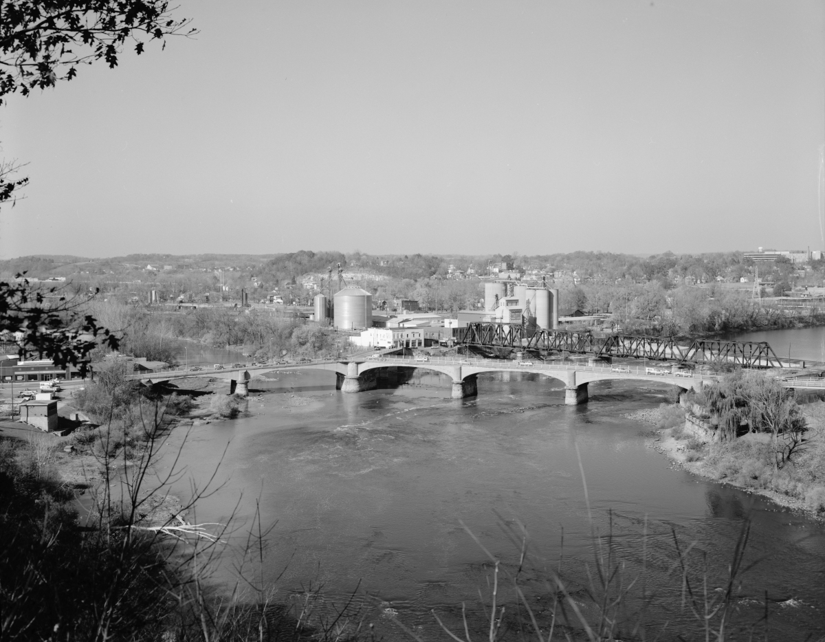
Significance
The Y-Bridge was one of the early bridges in the United States to use concrete and steel construction. At the time it was built, it was the only bridge in the United States with a Y configuration. The bridge was designed by Edward Landor, who used the Thacher patent system of construction. The Y-Bridge, along with the three wooden bridges it replaced, has been a part of the national road system since the eighteenth century.
Report of the Historic American Engineering Record (HAER No. OH-22) by Jean P. Yearby, 1986
Historical Information
The crossing at the confluence of the Muskingum and Licking Rivers has a long history as part of the national highway system. In 1798, Zane's Trace, the first road sanctioned by Congress, was completed between Wheeling and southwest Ohio and, at this point, passed through Zanesville. In 1826, the National Road reached Zanesville, and it too used this point for crossing.
To accommodate the crossing, a series of bridges, all of a Y formation, were built on the site. Three wooden bridges preceded the present concrete and steel structure. The first three-branched structure was built by Rufus Scott in 1813-1814. It was a fragile, uncovered wooden bridge. Although repairs were made during the following four years to keep it passable, the entire structure collapsed in 1818. A second bridge was built in 1819. It was a partially covered structure with cambered lower chords which gave it a hilly or rolling appearance. After thirteen years of service, the second Y-shaped bridge was condemned as unsafe.
The third bridge, a covered timber bridge, was completed in December 1832. It stood for sixty-eight years, until 1900. The county commissioners closed the bridge in January of that year, following an examination and report by the Osborn Engineering Company, consulting engineers from Cleveland, Ohio. The company reported that the bridge was unsound and not fit for use. At the same time, the commissioners sought proposals and funds for the construction of a fourth bridge at the site.
In April 1900, the Muskingum County Commissioners awarded the contract for plans and specifications and superintendence of construction of the new bridge to the Osborn Engineering Company. The American Bridge Company won the design competition for the bridge. Edward Landor designed the Y-Bridge and supervised the construction as the resident engineer- The Berlin Bridge Company of New Berlin, Connecticut, was awarded the construction contract. In April 1902, construction was completed. Base construction cost of the Y-Bridge was $188,000, with additional expenses amounting to $6,316 for a total cost of $194,316.
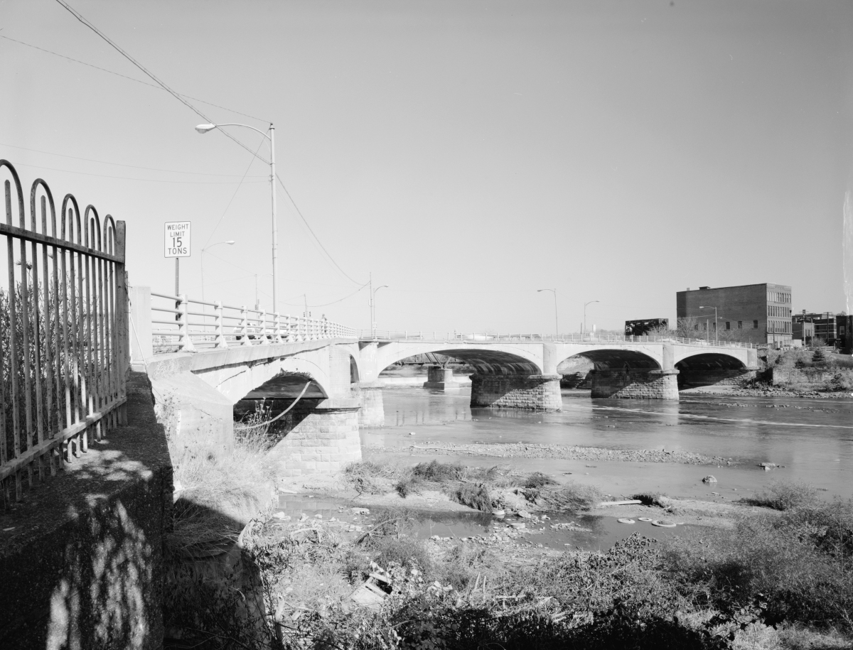
The Y-Bridge was opened to the public in January 1902. It was one of the first bridges in the United States in which concrete-steel construction was used, and it was the only Y-shaped bridge in existence at that time. The 2anesvile Courier claimed it had "for one of its spans what is said to be the flattest arch ever used in a bridge built for ordinary traffic."
Thr Y-Bridge carried traffic for seventy-nine years. It was the only bridge in Zanesville which survived the great flood of 1913. During the floods the bridge's concrete parapets were demolished by railroad cars which floated down the river after being washed off the bridge immediately upstream to the Y-Bridge. The river rose to a depth of 51.8 feet, completely submerging the Y-Bridge. After the waters receded, the Y-Bridge was the only bridge in Zanesville which, with some repairs, could still be used. All the other bridges in Zanesville that crossed the Muskingum River had collapsed.
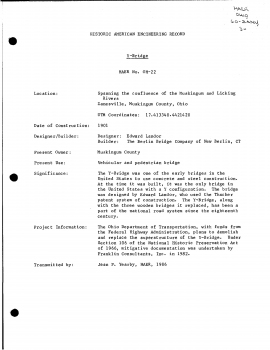
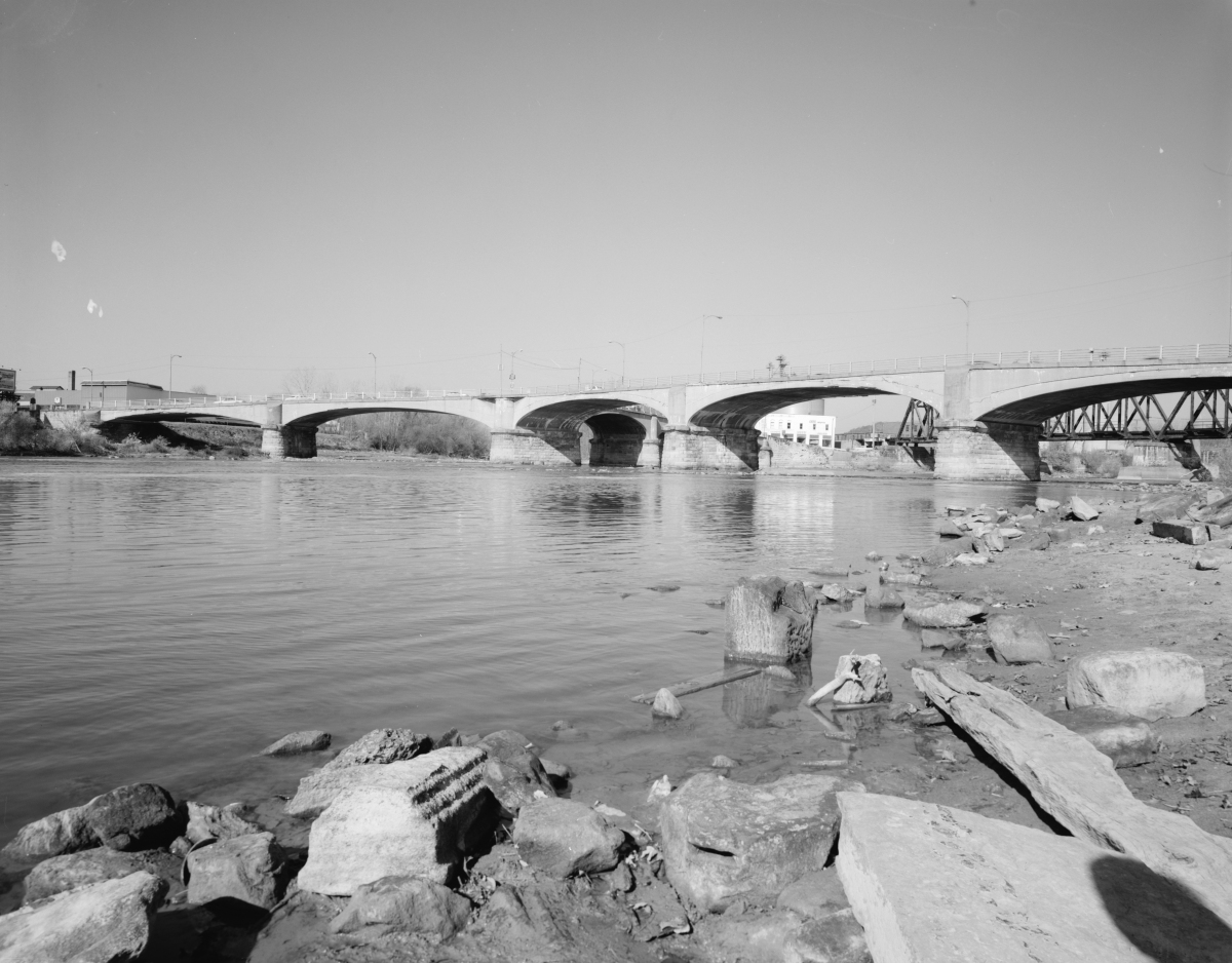
Structural Information
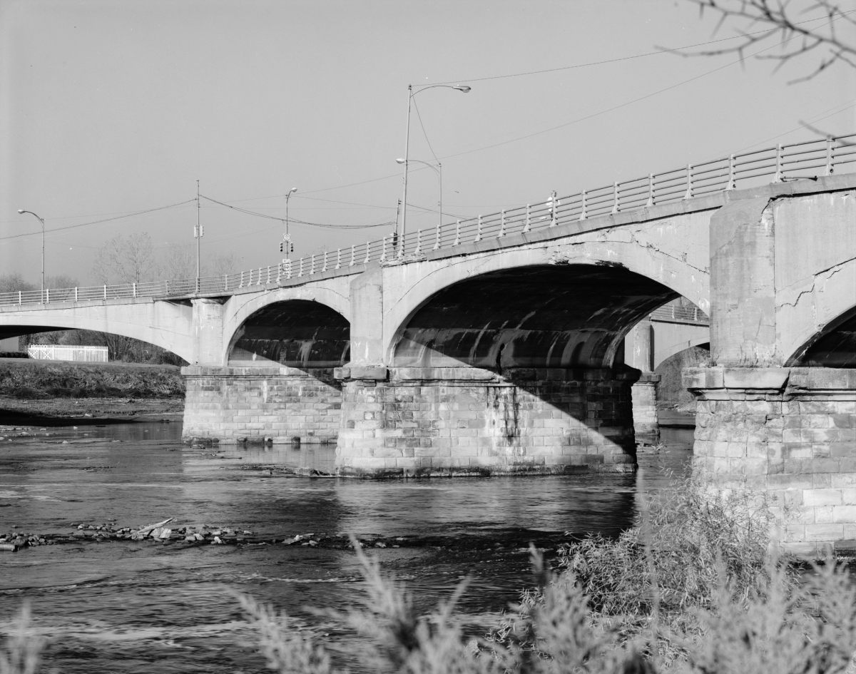
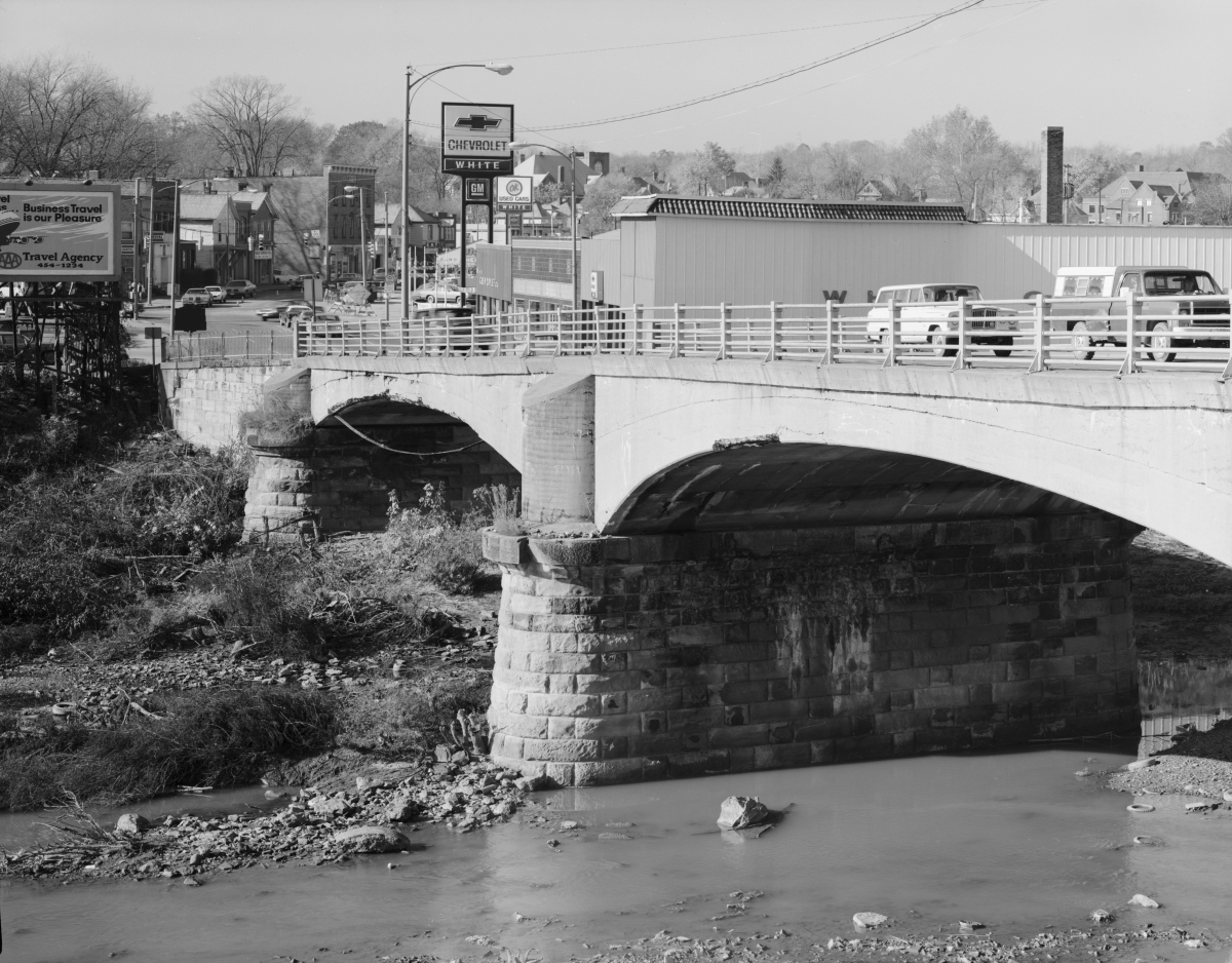
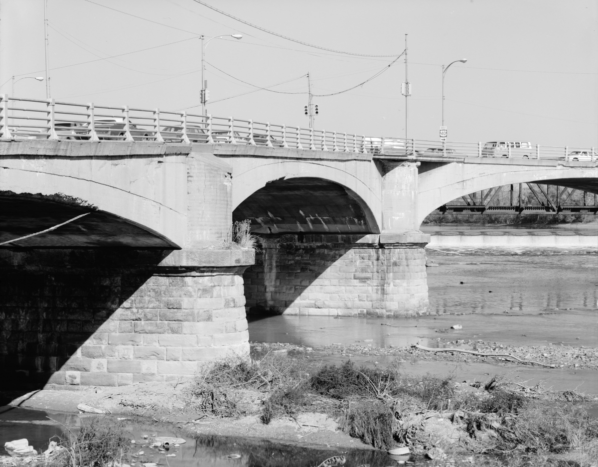
The bridge consists of eight elliptical reinforced concrete spandrel-filled arches, resting on stone masonry piers and abutments. The piers are placed directly on the bedrock with only a concrete leveling course between the stone masonry and the bedrock. It is probable that the stone piers from the previous bridge were used in the 1900 construction. The piers were simply redressed and the cut-waters rounded at both ends. The form work for the concrete spandrel arches was apparently supported on heavy timber falsework. Construction joints in the arches are spaced six feet apart, indicating the size of the concrete lifts used.
The deck rises to a height of forty feet above the river bed at the center pier. This height and the flat elliptical shape of the arches were obviously made to obtain as large a waterway opening as possible.
In designing the bridge, Landor employed the system patented by Edwin Thacher and named after him. In this system, steel bars are embedded in concrete arch rings in two layers. These steel bars are 3/4" x 5" and have steel rivets driven into them to increase their grip. One layer of bars is two inches from the intrados and the other two inches from the extrados. The bars are spaced on approximately three-foot centers. The thickness of the arches and the width of the steel bars are varied according to span length. Three widths of steel bars were used in the Y-Bridge: 3, 4-1/2, and 5 inches. Fifteen pairs of steel bars were used in each span. The bars were placed continuously over the piers and anchored into the skewbacks of the abutments an the center pier.
The stress diagrams used in the design were developed by Edward Landor with the assistance of F. E. Barnes. Architectural details were drawn up by an unidentified architect.
As indicated in the bridge's history, it survived the 1913 flood with only superficial damage. The bridge stood relatively unchanged until 1953. In that year, a partial failure took place in the first span of the Linden Avenue leg. Part of the spandrel walls and the railing were damage and construction joints in the soffit of the arch opened up. The damage was repaired and the existing fill of sand, gravel, and cinders was replaced by granular slag fill in order to reduce dead load. The open joint was repaired by pneumatically placed mortar.
In November 1970, the engineering firm of Modjeski and Masters inspected the bridge. They reported that there were weak areas beneath the railing supports. There was also concrete loss in the cover over the steel strap reinforcing. They described the transverse joint in Structure 3, Span 1, as follows: "The joint is slightly open and gives the appearance of a crack as its edges are jagged and show minor spalling." Apparently the pneumatically placed mortar from 1953 was starting to fall out.
The report ends with this conclusion: "The inspection of the Y-Bridge revealed the structure to be generally in good condition." The soundness of the bridge does not seem to have been affected by age. Some portions of the arch barrels and the roadway show the effects of weathering and wintertime operation. A minimum of concrete arch and roadway repair where needed, as outlined in this report, and close attention to proper maintenance should enable the structure to remain in serviceable condition for many years.
In November 1977, Franklin Consultants inspected the bridge again and updated the Modjeski and Masters report. Their report was supplemented by an investigation of the concrete strength of the spandrel arches. Franklin Consultants selected eight locations in the Y-Bridge for core samples and the H. C. Nutting Co. tested these cores in their laboratories for compression strength and chloride contamination. The compressive strength varied fom 4,920 psi to 10,000 psi and the chloride fom .004% to 0.67%.
The report further pointed out that the damage construction joint in Span 1 of the Linden Avenue structure showed increased signs of deterioration and a further investigation should be made to see if any damage had been done to the reinforcing steel. The report found the same deficiencies which were mentioned in the 1970 report and added that the spandrel walls showed extensive pattern or map cracking and that efflorescence stains were visible at most of the construction joints in the barrel arches, indicating moisture seeping through the barrel arches from the inside fill. The report concluded with suggested maintenance and repairs in order to insure continued use of the bridge.
An update of the inspection report from November 30, 1977, was made on September 6, 1979. This inspection was mostly concerned with the Linden Avenue span. An access hole had been dug over the construction joint in question. This investigation was not conclusive but it was decide to place a fifteen ton load limitation on the span until the investigation could be completed.
An underside inspection of the first Linden Avenue span was completed on September 19, 1979. It was found that the joint had open about 1/4 inches on the tension side to a depth of 7 to 8 inches and that some of the bottom reinforcing steel had broken at the heads of the rivets, apparently from tension. The previously-set fifteen ton limit was lowered to five tons and a monitoring of control points on this span was started to detect any further downward movement.
On December 13, 1979, the County Enginer detected a downward movement of .02 feet of the control points and it was decided to close this part of the bridge immediately. In order to reopen the Linden Avenue span, the County Engineer suggested that a temporary falsework be erected to support the span so that the bridge could be opened for a maximum live load of five tons. This was accomplished in January 1980. At this time, it was determined to make all the necessary repairs to the superstructure and early coordination was initiated for those repairs in January 1980.
A subsequent inspection of the bridge in August 1980 indicated that the repair project as originally conceived was no longer feasible and that the superstructure would have to be replaced.
In addition to the problem with the failing Span 1 of Structure 3 , Span 2 of Structure 1+ now started to show signs of overstressing. There were no signs of broken reinforcing steel, but a beginning opening of the construction joints at the soffit of the arch was evident. The span also responded to live load to an extent unacceptable for a concrete arch. Taking these factors into consideration, together with a slight dip in the profile of the road in this span, there was a general consensus among the engineers performing the inspection to reduce the maximum load for the span to fifteen tons, thereby excluding heavy trucks from the use of the weakened span. The bridge is at present being monitored continuously to detect any further deterioration in strength.
Report of the Historic American Engineering Record (HAER No. OH-22) by Jean P. Yearby, 1986
Participants
Contractor
Relevant Web Sites

- About this
data sheet - Structure-ID
20087320 - Published on:
27/10/2023 - Last updated on:
27/10/2023
Structurae cooperates with


