
Renewal of the rope coating on the Severin bridge in Cologne
The repair of the Severinsbrücke required a complete renewal of the corrosion protection of the pylon (outside) and the cables. This required section-by-section construction work.
Media
Renewal of the rope coating on the Severinsbrücke bridge in Cologne, Germany.
1 Introduction
1.1 History of the bridge
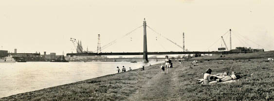
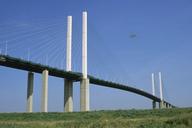
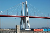
The Severinsbrücke bridge in Cologne (Fig. 1) connects the Severinsviertel district with the Cologne-Deutz district on the right bank of the Rhine
| Year of construction: | 1956-1959 (image 1) |
| Cost: | 25.3 million DM |
| Support system: | Cable-stayed bridge with A-shaped pylon | .
| Pylon height: | 77.2 m |
| Architect: | Gerd Lohmer |
| Engineer: | Fritz Leonhardt |
| Building material: | Steel |
| Steel weight: | 8300 t |
| Span: | 302 m |
| Width: | 29.5 m |
| Total length: | 691 m |
| Color: | Cologne bridge green |
| Number of cables: | Each 6 cable bundles upstream and downstream with different numbers of fully locked individual ropes (4, 9, 12, 16 ropes) with individual diameters of 69 mm, 73 mm and 85 mm respectively (per bundle same individual rope diameters) |
The cable bundles run partly over saddle bearings, partly end single cables in the pylon.
The shape of the cable bundles is square or rectangular. The cable bundles run from about the middle of the walkway diagonally to the pylon head above the streetcar rails and are also slightly rotated against the horizontal axis in space.
1.2 Previous Rehabilitation Measures
.Starting in 1988, the corrosion protection coating of the Severinsbrücke was fully renewed for the first time. This measure affected the lower view, the pylon and the cables.
The used trolley systems did not yet have to comply with maximum pressures on the cables. Due to this fact, the trolleys were much easier to dimension.
The coating systems used on the soffit and pylon surfaces were already systems in accordance with sheet 87 of DB's TL 918 300 or ZTV KOR-Stahlbauten (zinc dust primer coating; epoxy resin intermediate coating; polyurethane deck coating).
On the cables, after blasting, the then approved coating system of Sigma Unitecta was used, usually consisting of CM primer, partially zinc chromate (Folic PCR) and 2K-PUR-Folic Ena EG SQ, or Bicompon 1432 SQ. The insides of the cables have not been repaired since construction and are coated with a primer according to DV 807, substance no. 4634.55. The individual wires of the cables were pulled through a lead immersion bath (DV 807, Fabric No. 4634.75) prior to capping. The cables were to be fully injected. A protective roof was also erected below the pylon at that time to protect against falling parts.
2 Repair Measures as of 2010
2.1 Work to be carried out
Complete renewal of the corrosion protection of the pylon (exterior) in accordance with DIN EN ISO 12944 or ZTV-ING Part 4 Section 3 - Corrosion protection of steel structures. The existing coating was to be removed by compressed air blasting (standard degree of cleanliness: SA 2 1/2). The coating structure was selected in accordance with Sheet 87: Primer coating: 2K-EP zinc dust (687.03) - 70 μm Edge protection: 2K-EP zinc phosphate (687.06) Intermediate coat: 2K-EP micaceous iron oxide (687.12/13) - 1 × ZB (above spray area) - 2 × ZB (spray area) - 3 × ZB (water change zone) - 80 μm each Top coat: 2K-PUR - Cologne bridge green - 80 μm
Full renewal of the corrosion protection of the cables in accordance with DIN EN ISO 12944 or ZTV-KOR steel structures (2002 edition) Table A.2, component number 7 for non-galvanized cables. The coating structure was selected as follows: 2 × primer coat: Sika Cable FE Primer - 50 μm each. 2 × intermediate coat: Sika Cable TOP 1 - 3 × ZB in the de-icing salt spray area (up to 15 m above the bridge deck) - 150 μm each Top coat: Sika Cable TOP 2 - Cologne bridge green - 60 μm
Puttying after the 2nd GB is carried out with Sika Cable Flex 1, a 2K PUR joint putty specially developed for the cable coating system and tested in the present system.
The following work sequence was provided:
- Removal of the cable clamps .
- Removal of the joint putty .
- Removal of the old coating by means of compressed air blasting (standard degree of cleanliness SA 2 1/2)
- Application of the primer coatings .
- Cementing the rope gussets/throats
- Application of the 1st intermediate coating
- Installation of the newly coated cable clamps (2 × GB, 1 × ZB)
- Application of the 2nd and 3rd (de-icing salt spray area) intermediate coatings .
- Application of the top coat .
In addition to these main services, the cables and support structures inside the pylon head, as well as the upper and lower cable cover hoods, were to be corrosion-protected from the inside and outside. In addition, new radar lances were to be installed.
2.2 Construction Aids
The pylon will be scaffolded in sections and provided with dust-proof tarpaulins.
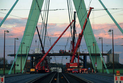
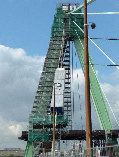
To protect against falling parts, a protective roof will be installed, which will be secured with a plank covering, a protective foil and a sheet metal layer to prevent falling objects from penetrating (Fig. 2). For material transport, a fixed elevator, also approved for passenger transport, will be installed to reach the pylon head.
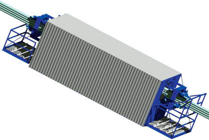
The cables will be processed from three working platforms (one each for cables 1/6, 2/5 and 3/4), each designed with a length of 6 m and adapted to the different inclinations of the cables and firmly enclosed with metal sheets (Fig. 3). The platforms receive type approval and are inspected by TÜV on site after installation and each modification. The platforms terminate at stations above the bridge deck. They were originally intended to pull themselves up on steel cables stretched between the bridge deck and the pylon with tirak hoists attached to the platforms.
The lower sections of the cables (up to about 10 m above the bridge deck) will be worked on from leveled off stand scaffolds.
3 Concept for processing the cables
3.1 Special features on the cables
The cables are rectangular or square cables - as a result, there are relatively large gaps between the fully closed individual cables inside the cables. The course of the cables is oblique from the anchorage in the box girder to the center of the pylon head; therefore, full scaffolding is not possible. In addition, there is an inclination of the bundles against the horizontal axis (transverse to the longitudinal axis of the cables), which may result in a one-sided load on the trolleys.
3.2 Cable traversing systems
Cable traversing systems shall be designed to compensate for the special features of the position of the cables in space and to allow safe working within the systems. Furthermore, safe access shall be provided.
The trolleys must be designed so that the surface pressure on the cables does not exceed 2.5 N/mm². This requirement represented a first. The top coat must not be driven over and, according to the tender, should be applied from risers. For the basic application of the top coat, the consortium provided a balcony at each platform so that the top coat can be applied from the outside when the system is shut down and no longer has to be driven over. Thus, risers are only required for touch-up work and possible acceptance.
Compliance with the permissible pressures was ensured on the one hand by the number of individual rollers per trolley (4 rollers per running side). Furthermore, extremely soft rollers made of a special plastic were used. The combination of these properties, coupled with adaptation of the rollers to the different individual rope diameters through appropriate design of the running surfaces (milling out), then led to compliance with the conditions specified by the tender.
3.3 Decementing the rope gussets
Due to the elastic structure of the joint putty, the decementing of the rope gussets/throats is carried out with special tools prior to the blasting work, as it is not possible to blast off the putty. The decementing is carried out as deep as possible into the root in order to be able to optimally prepare the surface for the subsequent primer coatings.
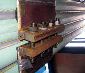
3.4 Auxiliary clamps
After the initial decementing work in the area of the stand frames, it was determined on the basis of the situation found that after the removal of the main clamps, auxiliary clamps must be installed to secure the position of the cables. The auxiliary clamps are installed successively during the dismantling of the main clamps in such a way that the auxiliary clamp is installed first before the main clamp can be dismantled. Disassembly and reassembly of the auxiliary clamps are carried out in the same way. For the complete processing of the cables, an additional auxiliary clamp is kept available in each case, so that the auxiliary clamps can also be relocated without any problems (Fig. 4).
3.5 Blasting and coating work
For the blasting and coating operations, the supply lines (blasting and suction hoses, control cables) are fastened below the cables with the help of tension belts at a distance of approx. 50 cm. For safety reasons, only new hoses and cables are laid. The blasting work is carried out from top to bottom. This is also done for the coating work. During the shutdown, the supply lines are successively dismantled.
4 Changes during execution
.4.1 Grouting defects
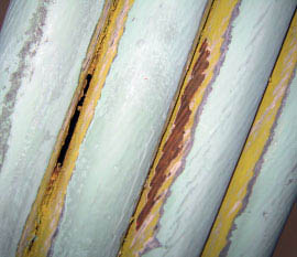
During the decementing of the cable gussets within the stand frames, isolated hollow spots were initially found within the cables. These were of the type that old blasting debris was partially leaking from cavities inside the cables through the open gaps found (Fig. 5).
Due to this fact, even before the first 6-m stage was installed, it was determined for safety reasons that auxiliary clamps were essential.
Furthermore, it was determined that the cavities found had to be post-injected. For this post-injection, specially made special packers are set as injection and venting packers prior to cementing. For this purpose, the individual ropes must be carefully expanded at the appropriate points with wooden wedges. This is followed by cementing. The cavity is then grouted using the system-compliant 2-component grouting material Sika Cable Flex 2 with the aid of an appropriate device (e.g. injection pump or airless pump) following the cable upwards until the material emerges at the next packer. The packers are removed after the material has hardened and the putty seams are completed.
The previously found blast debris was removed as much as possible by blowing it out.
From the situation found on site, the question arose as to the further procedure for working from the cable access facility, provided that the cavities would continue upwards in the course of the cable.
Under all circumstances, water access to the cable interior had to be prevented. However, if the traversing system were to continue after an area had been decemented (according to the original design), voids might lie open for extended periods of time and be exposed to the elements. This would require a conceptual change to the workover.
4.2 Change in location of cables within cables
.When the cables were decemented, it was also noted that the cables were obviously no longer rectangles or squares, but rather trapezoidal shapes. The advantage for the cable bundles was that the narrow side of the trapezoid had so far usually been found at the top. This meant that the upper individual cables were very close together. For positional reasons, this fact made it difficult for water to reach the inside of the cable.
5 Conceptual adaptation for the changed conditions
.5.1 Stage extension
Due to the situation found (injection faults) also in the upper area of the cables, adjustments to the work planning were necessary during execution.
Together with the client, it was decided, also in order not to let subsequent projects get out of control in terms of scheduling, to do everything possible to minimize the construction time extension that was becoming apparent due to the additional work steps. This is necessary because the Rhine bridges in Cologne are a sensitive structure in terms of the flow of traffic across the Rhine. Detailed planning of the upcoming repair measures on the Cologne Rhine bridges, over a period of years, is therefore essential.
In the present case, it was decided to limit the traffic facilities to a maximum dimension (max. compression must be observed) in order to minimize the risk of water entering the spaces between the cables, while at the same time ensuring a reasonable workflow (Fig. 6).
The lengthening of the working platforms resulted in a change in drive technology. The weight of the larger rigs necessitated much larger tiraks (electric continuous winches). These motors had to be installed on the protective roof. This necessitated reinforcements on the protective roof in the area of the mounted endless winches. The endless winches (tiraks) now pull the cable traversing systems over pulleys installed on the pylon head. A winch operator is permanently stationed on the protective roof, who is in constant radio contact with the employees in the access systems, operates the motors on instruction from the platforms and constantly checks them.
The extended travel units will be provided with a shuttle so that they can remain at the point of current processing should cable areas be open. Employees will then use the shuttle to get to the stages and the station. Cable 3/4 stages will not be extended as there is only a void. Water ingress is not a problem in this case, as water cannot seep into deeper cavities should voids occur. It can escape again and the rope dries again.
5.2 Pre-cementing
In addition, it was determined that any voids found during decementing of the cable gussets must be provisionally cemented and then grouted before the further work steps can be carried out. This measure should completely exclude water ingress to the cable interior.
All the measures described lead to the assurance of the quality of the work to be carried out and ensure that the extension of the construction time is within a tolerable or plannable range.
6 Conclusion
Due to the uniqueness of the Severinsbrücke in terms of its special design features, it was not possible to plan in advance for all the problems that arose, even under the new conditions from the invitation to tender. The problems that arose required flexible planning of the measures to be taken during construction.
Currently, the planned completion date of the current construction project is in 2013.
Author of this post:
Dipl.-Ing. Frank Sczyslo, Hans Tiefenbach GmbH,
Theodor-Heuss-Strasse 34, 47167 Duisburg
Josef Teupe, Teupe & Sons Scaffolding Ltd.
 Teupe & Söhne Gerüstbau GmbH
References

Structure Types
Relevant Websites

- About this
data sheet - Product-ID
7233 - Published on:
14/01/2015 - Last updated on:
03/03/2023