

General Information
Project Type
| Structure: |
Deck arch bridge |
|---|---|
| Function / usage: |
Road bridge |
| Material: |
Concrete bridge Structurae Plus/Pro - Subscribe Now! |
| Plan view: |
Structurae Plus/Pro - Subscribe Now! |
Awards and Distinctions
Location
| Location: |
Philadelphia, Philadelphia County, Pennsylvania, USA |
|---|---|
| Copy of: |
Adolphe Bridge (1903)
|
| Coordinates: | 40° 1' 56" N 75° 11' 59" W |
Technical Information
Dimensions
| width | 18.29 m | |
| total length | 146.30 m | |
| height above valley floor or water | 44.81 m | |
| number of lanes | 2 | |
| arch | arch span | 71.02 m |
Materials
| piers |
un-reinforced concrete
|
|---|---|
| arch |
un-reinforced concrete
|
| abutments |
un-reinforced concrete
|
Significance
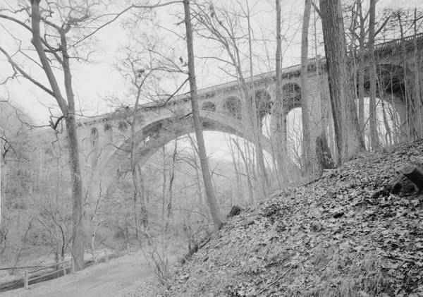
When completed in 1908, the Walnut Lane Bridge was the world's longest concrete arch bridge, with a main span measuring 233'-0". Taking inspiration from a 1904 masonry arch bridge in Luxembourg, Webster and Quimby's two-rib, open-spandrel design uses a minimum of reinforcing steel. The bridge crosses Wissahickon Creek in Fairmount Park, a National Register-listed historic district.
Introduction
The Walnut Lane Bridge is a significant example of a concrete arch bridge that set world records upon its completion in 1908. Its unusually large main span made it the longest (233'-0") and highest (147'-0") concrete arch bridge. Rubble concrete, a mixture with large stones embedded to increase shear strength, was used in structural portions of the bridge. Reinforcing steel was sparse, however, limited to critical points where the concrete was likely to crack on account of shrinkage or other tensile stresses. Set in the romantic landscape of Philadelphia's Fairmount Park, the bridge's graceful and sweeping arches appealed to the masses. With this concrete bridge, the city of Philadelphia was set on a course for designing and erecting aesthetically appealing concrete bridges well into the twentieth century.
Description
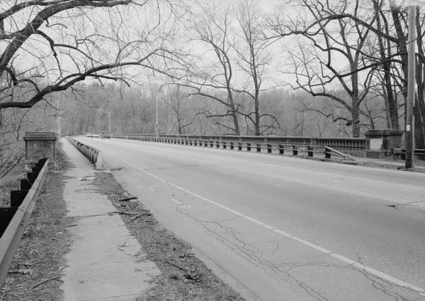
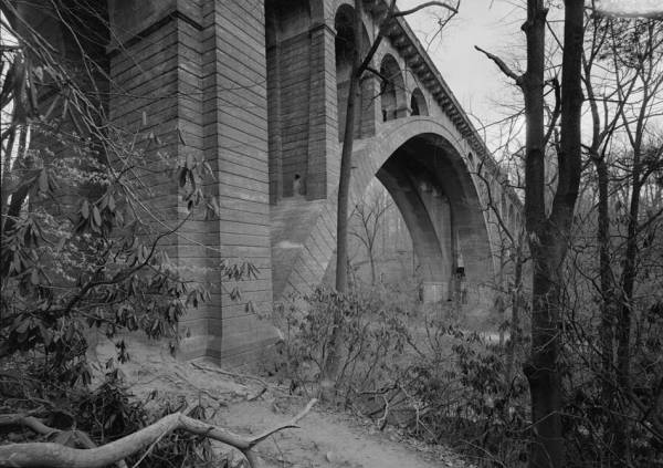
Carrying Walnut Lane over Wissahickon Creek, the Walnut Lane Bridge was the first span to directly connect the neighborhoods of Roxborough and Germantown in northern Philadelphia. Densely wooded hillsides hide the steep contours of the valley below, while at either end of the structure are late nineteenth- and early twentieth-century residences. The Walnut Lane Bridge has six spans, all three-centered, open-spandrel concrete arches, for a total length of 585'-0". The main arch has a clear span of233'-0" and rises 70'-3" from springing line to crown, for a total height of about 147'-0" above the valley floor. Eight semi-circular spandrel arches, each 20'-0" long, support the deck above the arch ribs. On the approach spans, solid walls conceal the open-spandrel construction. Two arches on the north approach have a clear span of 53'-0", as do three arches on the south approach. All of the piers, abutments, and wing walls extend downward to bedrock, which is a mica schist. The footings had to be built around an existing 30"-diameter water main running parallel to, and 6'-0" south of, the bridge's center line. The roadway is 40'-0" wide from curb to curb, with concrete sidewalks on either side, which measure 10'-0" wide from curb to parapet.
The Walnut Lane Bridge's main span takes inspiration, both structurally and aesthetically, from long masonry arch spans in Europe, especially the Pont Adolphe, a bridge over the Patrusse River in Luxembourg. The Walnut Lane Bridge actually contains a large quantity of stone, in the form of rubble concrete. This material consists of large stones embedded in the concrete mixture, arranged in such a way to provide additional shear strength. Specifications for the bridge's construction stipulated, for example, that flat stones "not less than one man size," the size which an average worker was capable of lifting, be "placed in radial planes as close together as practicable, always edgewise to the centering."
In contrast, there is very little steel reinforcement in the main arch span. Its two arch ribs taper from 21'-6" wide by 9'-6" deep at the springing line to 18'-0" wide by 5'-6" deep at the crown. Yet there are only three 1"-square iron bars placed below each of the transverse spandrel walls, making the bridge essentially an unreinforced or mass concrete structure. The ribs are incised with radial lines, creating the impression of oversized stone voussoirs. Although serving a decorative purpose, the voussoir lines also disguise joints between separate concrete pours. Each rib was poured as a series of twenty-two large blocks, each four to seven voussoir units in length. The blocks were poured symmetrically on either side of the falsework, leaving seventeen one-voussoir gaps between them. These gaps were filled with concrete after pre-compressing the arch as described below.
Above the main arch span, four lines of spandrel arches form continuous longitudinal girders supporting the deck. Their transverse spacing is 14'-0" on center above each rib, and 20'-0" on center between the ribs. The spandrel arches are carried on posts measuring 4'-0" square and placed 24'-0" on center, with the outside pairs braced by transverse walls typically 2'-0" thick. Only the tallest spandrel posts are reinforced with six I "-square iron bars where they intersect the arch rib. The approach spans have a similar arrangement of transverse walls above each rib, with the spandrel posts replaced by solid spandrel walls 2'-6" thick.
The floor system consists of reinforced concrete jack arches spanning between transverse floor beams. To resist the arches' outward thrust, the floor beams are tied together by 7/8" diameter rods. The beams are fully encased in concrete and placed 6'-0" on center, except above the transverse walls. In those locations, the floor slab is broken by a tongue-and-groove expansion joint, with the tie rods anchored into the slab on either side. One end of the slab is cast integrally with the wall, while the other is free to slide on a zinc bearing, analogous in function to the expansion roller ofa truss span. The shorter beams above the ribs are 15"-deep rolled I-beams weighing 42 pounds per foot, cantilevered outward to support the sidewalk brackets. Longer beams spanning between the ribs are 20" deep, weigh 65 pounds per foot, and sit at a slightly lower elevation. This is because the middle 20'-0" of the deck slab, between the two arch ribs, is depressed 11-1/2" to accommodate future streetcar tracks. According to construction drawings, this depression was filled with cinders before paving the entire roadway with a 6"-thick layer of bituminous concrete, followed by a 3-1/2" asphalt wearing surface. The Philadelphia Rapid Transit Company evidently planned to lay tracks across the bridge shortly after its opening, but this never occurred.
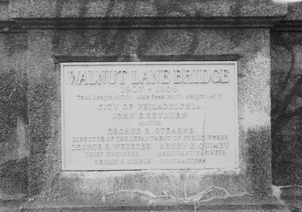
Among the bridge's notable ornamental details is the reinforced concrete sidewalk and balustrade. Supported on the cantilevered floor beams, the sidewalk is reinforced with I" square rods running longitudinally and 1/2" square rods running transversely. The ends of the floor beams are encased in concrete brackets. At the same 24'-0" intervals as the spandrel posts, the brackets are slightly larger and emphasized by pilasters in the balustrade above. A curb at the outside edge of the sidewalk forms the bottom rail of the balustrade, onto which precast concrete balusters, 884 in all, were attached. The balusters have a hard, smooth, gray finish and were cast by using one set ofmolds repeatedly.8 Over the main span piers, the sidewalk and balustrade project outward an additional 3'-0" on either side, forming rectangular recesses that originally held cast-iron light standards (since replaced with modern aluminum fixtures). Were streetcar tracks installed on the bridge, the standards would have formed the bases of poles supporting overhead wires.9 As a commemorative detail, the bridge has four plaques, one at the base of each main span pier and one at each end of the deck, set into the balustrade. Those on the piers record the start of construction, 1906 on the west pier and 1907 on the east. The plaques at deck level reflect the official (but less accurate) dates of construction, 1907-08.
Concrete Bridge Design in Philadelphia
With its light reinforcement, the Walnut Lane Bridge is a transitional form in the development of reinforced concrete during the early decades of the twentieth century. Previously, concrete possessed the same structural properties as masonry, providing excellent compressive strength but little or no ability to resist tension. With the advent of iron and, eventually, steel reinforcement, both compressive and tensile properties were enhanced. Once engineers came to understand of its structural behavior, reinforced concrete was an appealing alternative to all-steel bridges. Concrete could be poured by an unskilled workforce, using materials readily available in eastern Pennsylvania, and did not require painting afterward. Furthermore, concrete had the aesthetic advantage in holding whatever ornamental detail was built into the formwork. City engineers therefore saw and seized upon the usefulness of the concrete in urban and picturesque settings.
As Chief Engineer of the city's Department of Public Works and Bureau of Surveys, George S. Webster had long argued that a high-level bridge between Roxborough and Germantown would eliminate a hilly five- or six-mile detour into the Wissahickon Creek valley. Webster, a native Philadelphian, was born on 19 October 1855. He graduated with a civil engineering degree from the University of Pennsylvania in 1875 and immediately went to work as a civil engineer for the U.S. Centennial Exposition project in Fairmount Park. Between 1880 and 1892, Webster was employed by the City of Philadelphia's Engineering Department, overseeing various engineering and surveying projects. In 1892, Webster was appointed Acting Chief Engineer of the city's Department of Public Works and Bureau of Surveys. Webster became the permanent Chief Engineer on 1 February 1893, a position he held until 1915.12 Based on his prior work in the park, Webster knew the importance of maintaining the natural appearance of the Wissahickon Creek valley. He selected an arch design to avoid stream impediments. A steel viaduct was deemed inappropriate amidst the forested scenery. In a paper delivered to the 1909 annual meeting of the American Society of Civil Engineers, Webster explained why concrete was selected:
The development of the sphere of usefulness of concrete, and the city's extended experience in the use of it for arches, walls, and floors, with new and improved methods of manipulation and construction, whereby more nearly uniform character and value are obtained, and the adequacy and permanence of the material are assured, together with the great economy obtained through its use, influenced the adoption of concrete as the structural material of the bridge throughout, and it was designed so as to require steel reinforcement at only a few points.
Webster's assistant, Henry H. Quimby, was also responsible for the bridge's design and finish. Quimby was born in Womelsdorf, Berks County, Pennsylvania, in 1858. Between 1876 and 1900, Quimby worked his way up from office boy to civil engineer at the Phoenix Bridge Company in Phoenixville, Chester County. In 1900, Quimby moved to Philadelphia after accepting the position of Chief Engineer with the Philadelphia Rapid Transit Company to oversee elevated railway construction. Within several years, he became Assistant Engineer under Webster, assisting him in the design ofa number of the city's largest bridges. Quimby later used this experience in consulting on the design of bridges elsewhere in southeastem Pennsylvania. On 25 June 1948, Quimby died after suffering a stroke at age ninety.
Quimby developed the concrete finishes used on the Walnut Lane Bridge and other city structures. One process entailed adding a fine black aggregate to the concrete mixture, given the exterior a dull granite-like veneer, not to mention increased durability and uniform texture.15 Another process actually bore Quimby's name in published descriptions. ''The Quimby process," explained an article in Engineering Record, "consists of removing the forms while the concrete is still friable and washing it with water applied with scrubbing brushes," exposing the aggregate. These finishing methods provided the variety of surface textures found on the Walnut Lane Bridge.
Construction Sequence
Design and construction of the Walnut Lane Bridge consumed three and a half years. The process began in earnest on 13 July 1905, when the Philadelphia City Council appropriated $190,000 for the city's Department of Public Works and Bureau of Surveys to construct a new bridge across the Wissahickon Creek valley. Webster, his assistant Quimby, and their staff went to work on the design. They evidently considered three schemes: a steel viaduct at the estimated cost, a concrete arch for an additional $50,000, and a stone arch of similar design for an additional $100,000. Plans for a concrete arch were presented to the Board of Surveyors and approved on 19 April 1906. Toe city advertised for bids and opened them on 15 May, awarding the contract to Reilly and Riddle of Roxborough for $234,000. From the notice to proceed, issued on 5 July 1906, the firm had eighteen months to finish the project. The contract was amended in November to include up to $28,000 worth of additional services, with $1,800 allocated for bush hammering the underside of the main arch.18 Toe bridge was substantially complete on 14 October 1908, at a cost of$259,440 and more than nine months behind schedule. Even then the bridge carried only pedestrian traffic, with the roadway closed awaiting final grading of the approaches.19 A formal opening was held on 16 December.
Due to the main arch's immense size, the design of temporary falsework involved intricate calculations by the contractors, which city engineers later approved. For the sake of economy, the contractors used the same falsework twice: once for each rib. Four temporary concrete piers were built in the stream bed to support the falsework and provide a path for moving it from one rib to the other. The piers were excavated to bedrock and equipped with holes for inserting explosives after the falsework was dismantled. The falsework consisted of steel bents 20'-0" high, followed by two tiers of wooden trusses, 42'-0" and 54'-0" high, containing an estimated 370,000 board feet of timber. Completed on 1 April 1907 under the south rib, the temporary structure weighed an estimated 900 tons.
Timber was an appropriate material for the falsework, not simply because it was inexpensive and easy to erect, but because wood expands when wet. This property was used to great effect in constructing the arch ribs. Using an overhead cableway to deliver materials, the contractors began pouring the south rib by the end of April 1907. Soon thereafter, they began saturating the timber with water. The falsework swelled, widening the gaps or keys between the large blocks of concrete. After concrete was poured into the keys, the contractor allowed the timber to begin drying. The arch settled as the falsework shrank, compressing the keys. This pre-compression was intended to prevent shrinkage or tension cracks from appearing in the completed arch ribs. The concrete was allowed to cure from mid-June until July 22, when crews removed the wedges beneath the falsework. It took thirty men and three days to roll the falsework 34'-0" to its new position and re-insert the wedges. Concrete work on the north rib began on 16 September, again soaking and drying the timber to pre-compress the keys. Workers removed the wedges in early December and began dismantling the falsework. In order to remove the marks left by boards in the formwork, the city agreed to proceed with the proposed bush hammering. Another ten months passed before the bridge's deck was complete.
Conclusion
The Walnut Lane Bridge is significant for its bold use of concrete, a relatively new material in bridge construction. Its designers realized the bridge's potential to become a visually stunning structure set amidst natural scenery in Fairmount Park, then the world's largest urban park. The massive, graceful arch broke height and length records, and its erection was a well documented feat of engineering. Despite its size, the structural design is actually somewhat conservative, based on more traditional stone arch bridges. The Walnut Lane Bridge is essentially an unreinforced or mass concrete structure, not taking full advantage of reinforcing steel. Nonetheless, trade journals and popular magazines alike disseminated information throughout the country, helping to firmly establish concrete's reputation as an economical, low maintenance, aesthetically appealing material for medium-span bridges.
At the turn of the twentieth century, Fairmount Park was the world's largest urban park. From five acres surrounding the Fairmount Water Works in 1812, the park was expanded to more than 4,000 acres, including land formerly occupied by some of the city's wealthiest residents. The park also contains fourteen miles of tributaries and the Schuylkill itself, which formerly provided water power for a variety of enterprises. The earliest industries were mills in the Wissahickon Creek valley, with Richard Townsend operating a grist mill as early as 1686. Not until after the end of the Civil War was the west bank of the Schuylkill included in the park. Following the U.S. Centennial Exposition of 1876, the park matured into a picturesque combination of landscaped parkland and natural areas. The Exposition drew thousands of visitors to West Fairmount Park, a massive array of buildings and landscaped grounds. Celebrating a century of U.S. history and demonstrating futuristic applications of technology, the Exposition was an instant hit with the city and the world. In the wake of the event, the park became a year-round destination for refuge-seeking locals and day-trippers. Private ventures and various city agencies scurried to improve the urban infrastructure as West Philadelphia opened up for development. During the closing decades of the nineteenth century, modem iron and steel spans such as the Girard Avenue Bridge (1874), Falls Bridge (1895), and Strawberry Mansion Bridge (1897) were built to ensure reliable and safe access to West Fairmount Park and beyond. The Walnut Lane Bridge represents a second wave of bridge-building, the first of several concrete arch spans crossing the deep Wissahickon Creek valley to unite neighbourhoods on the east bank of the river.
Excerpt from Wikipedia
The Walnut Lane Bridge is a concrete arch bridge located in Northwest Philadelphia that connects the Germantown and Roxborough neighborhoods across the Wissahickon Creek in Fairmount Park. While drivers may cross the bridge too quickly to notice, the view from underneath the bridge has inspired many artists and writers, such as Christopher Morley. The design was copied from Pont Adolphe in Luxembourg.
The Walnut Lane Bridge was added to the National Register of Historic Places in 1988.
Construction
Construction began on July 5, 1906 and was completed on October 14, 1908. Over 40,000 tons of rubble concrete (containing a great amount of large stones, for greater shear strength) were poured into the falsework, which had been built from steel bents 20 feet (6.1 m) high and 370,000 board feet (870 m³) of timber, weighing about 900 tons. The bridge's six spans total 585 ft in length (178 m). Very little use was made of reinforcing steel, which was scarce at the time. The roadway is 40 ft (12 m) wide, flanked by 10-foot (3.0 m) reinforced-concrete sidewalks and pre-cast concrete balustrades.
The chief engineer was George S. Webster, assisted by Henry Quimby, both of the Philadelphia Department of Public Works. At the time of its construction, the bridge was the longest and highest concrete arch bridge in the world. While $240,000 was originally committed to the project, the figure rose to nearly $260,000 by completion (equivalent to nearly $6 million in 2008).
City Beautiful Movement
The bridge was a direct product of the City Beautiful Movement in Philadelphia in the early years of the 20th century. Seeking to provide community harmony and cooperation through improved public spaces, the bridge was viewed as an achievement that could unite the communities and cultures of Roxborough and Germantown in addition to inspiring a greater civic engagement. It was also believed that more beautiful construction techniques could help to reform a corrupt political system within the city. The Philadelphia community members rallied around the construction of the bridge and the opening was highly anticipated by all ages alike.
Opening
The bridge was opened on October 14, 1908 and was formally dedicated on December 16 of the same year. Students from nearby schools participated in the dedication ceremony by marching toward the middle of the bridge and singing "Hail Philadelphia." The ceremony ended with a reception at a local inn with the traditional Wissahickon meal of catfish and waffles.
Other bridges confused with the Walnut Lane Bridge
The Walnut Lane Bridge is often confused with other bridges in Philadelphia that are similar in name and construction. The Walnut Street Bridge crosses the Schuylkill River and connects University City, Philadelphia and Center City, Philadelphia. The nearby Wissahickon Memorial Bridge (aka Henry Avenue Bridge), which connects the East Falls and Roxborough neighborhoods of Philadelphia, is also often mistaken for the Walnut Lane Bridge. But the bridge most often confused with the Walnut Lane Bridge is the Walnut Lane Memorial Bridge, which replaced a cast-iron bridge over the Monoshone Creek and Lincoln Drive in Philadelphia in 1950 and is world-famous as a pre-stressed, post-tension concrete bridge.
Tragedy at the Walnut Lane Bridge
The Walnut Lane Bridge has a history of tragedies and deaths since construction began in 1906. In December 1907, the falsework (used to support the forms for pouring concrete) collapsed and sent about 20 workers plunging 150 feet (46 m) into the Wissahickon Creek. Martin Simpson was listed as the only worker to die during the tragedy while Bernard Mers lost an arm and James Lawson had both of his hands crushed. The crash drew neighbors out of their homes, as the sound could be heard throughout the valley.
Throughout the rest of the 20th century, stories of car crashes and suicides abound for the Walnut Lane Bridge. It was a common occurrence to see pictures of the bridge in the newspapers with a dotted line showing the path of a person's fall.
Centennial celebration
In 2008, Cliveden, a National Historic Landmark and museum in Germantown owned by the National Trust for Historic Preservation, celebrated the 100th anniversary of the completion of the bridge. Only a few blocks from the Walnut Lane Bridge, Cliveden hosted an exhibition and educational program on the construction of the bridge, featuring a collection of rare lantern slides. The exhibit ran from May through October.
Text imported from Wikipedia article "Walnut Lane Bridge" and modified on 23 July 2019 under the CC-BY-SA 3.0 license.
Participants
Relevant Web Sites

Relevant Publications
- (1909): Walnut Lane Bridge, Philadelphia. In: Transactions of the American Society of Civil Engineers, v. 65, n. 4 (December 1909), pp. 423-461.
- About this
data sheet - Structure-ID
20010874 - Published on:
05/12/2003 - Last updated on:
18/04/2024
Structurae cooperates with


