
General Information
Project Type
| Function / usage: |
Stadium / Arena |
|---|
Awards and Distinctions
| 2015 |
entry
for registered users |
|---|
Location
| Location: |
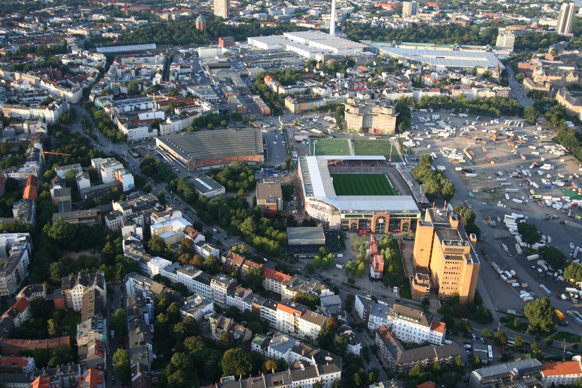
Hamburg-Sankt Pauli, Hamburg, Germany |
|---|---|
| Coordinates: | 53° 33' 16" N 9° 58' 4" E |
Technical Information
Dimensions
| Eastern grand stands | ||
|---|---|---|
| roof | width | 37 m |
| length | 120 m | |
Materials
| roof truss |
steel
|
|---|
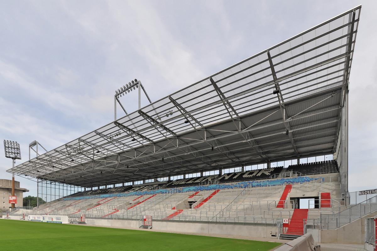
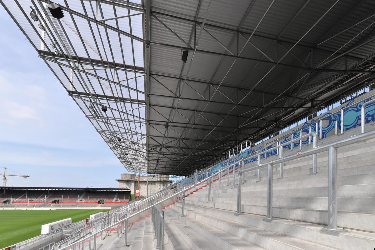
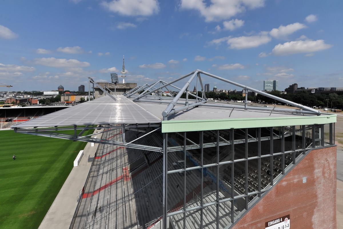
Roofing of the east stand of the Millerntor Stadium
Description of the construction
Task definition
The structural design for the roofing of an area of 120 x 37 m was based on clear boundary conditions, which consisted in the fact that only the rear 120 m long boundary line of the area to be covered and about two thirds of the side edges were available as support possibilities. Pylons and bracing outside this area were not possible, and it was also not possible to clamp a structure at the rear edge. Large interception girders, e.g. an arched truss or a main truss spanning over 120 m, had been considered as obvious and often executed constructions, but were rejected due to their optical dominance. The architectural problem was to find a „language“ that would form an architecturally convincing unit together with the existing west and south grandstand roofs and the north grandstand, which is still to be built at a later date. The characteristic feature of the west and south grandstands are triangular cantilevered lattice girders projecting towards the playing field, which are clamped into a solid structure in the west and rest on a longitudinal girder with two inner supports in the auditorium in the south and project 11 m inwards. For the new roofing of the east grandstand, a similar construction should be found, tapering to the front, with a perceptible maximum height of about 2.5 m.
Description of the supporting structure
The above-mentioned obvious solutions to this problem, i.e., for example, an arch spanning over about 150 m, a suspended structure spanning over 120 m with pylons and lateral bracing, or a massive truss truss spanning over 120 m, were outside the „architectural“, self-imposed requirements of the structural engineer and were rejected.
The solution resulted from knowledge of the load-bearing behavior of a three-sided drill-stiff slab, which does not support via edge-parallel bending moments but primarily via twisting moments in the corners.
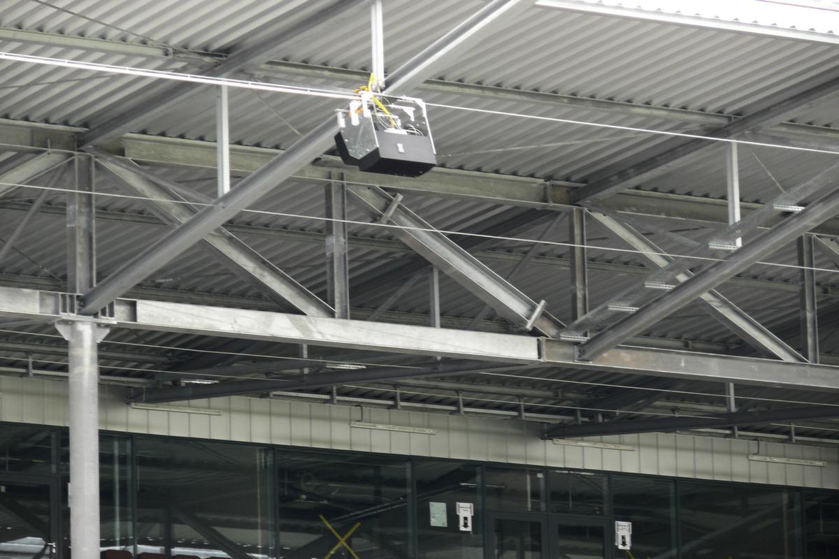
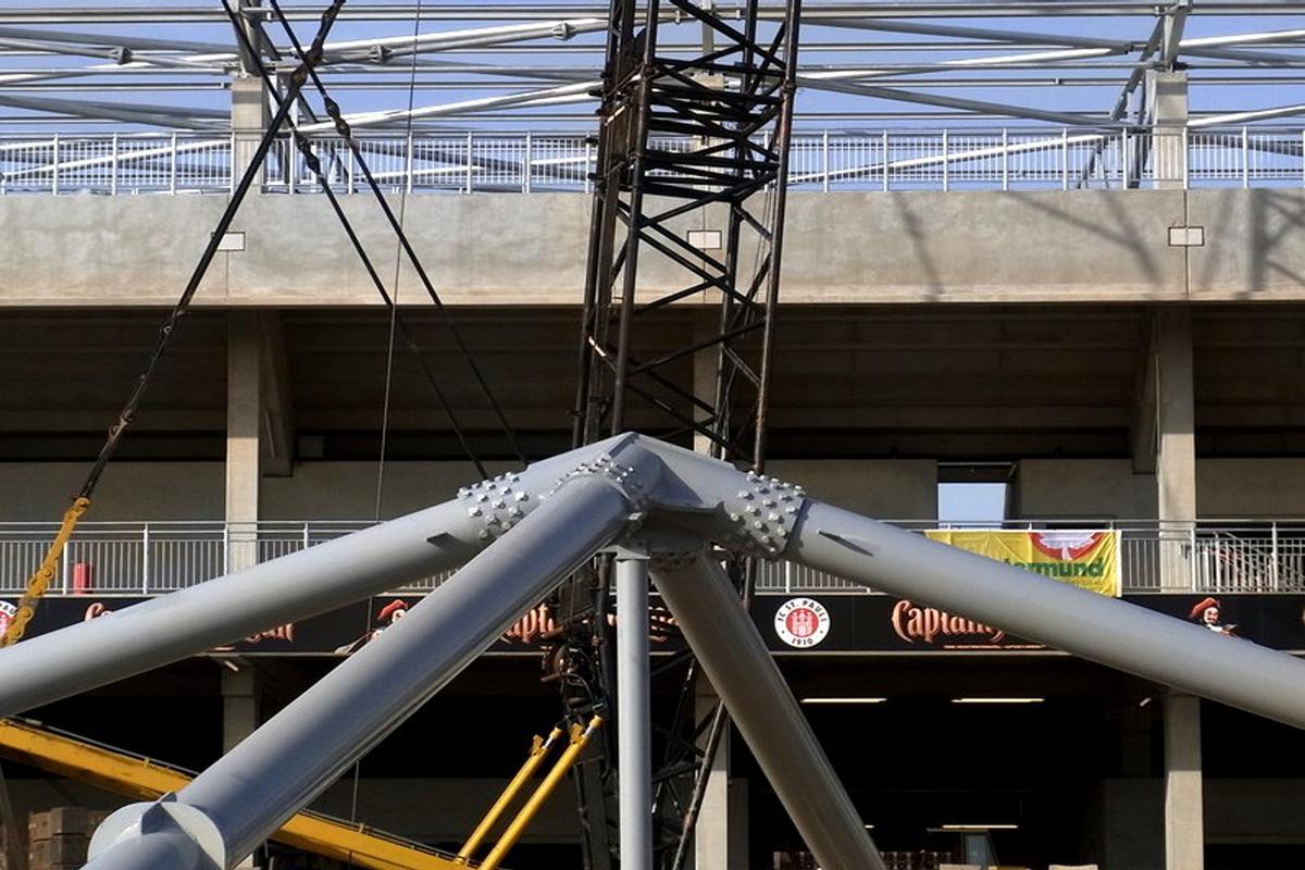
The chosen structure consists of a truss running in the longitudinal direction of the roof, which is attached to four special „antimetric torsion structures“, the four bar pyramids. This construction is modeled on the above typical moment profile of the three-sided supported plate with torsional moments in the corners and lifting corner forces (according to the plate theory 2 mxy). The effect of the torsional moments can be reinterpreted as bending moments which are mutually equal and run diagonally in the corners. In this case, large negative bending moments occur with tension at the top in the direction of the angle bisector and tensile support force in the corner, and equally large positive bending moments occur with tension at the bottom perpendicular to it. This effect is achieved for each pyramid by 2 diagonally running, intersecting, triangular trusses with only two bays each. The first main girder runs from the front corner support in the lateral façade, about 26 m from the rear corner, to the first quarter point of the rear longitudinal line, where it is supported on a short steel column on one of the cantilevered concrete columns. Its span is about 40 m. Its bottom chord runs horizontally, and its top chord forms a triangle 7 m high, in the ridge of which is a vertical bar leading to the center of the bottom chord. The second main girder is supported in the rear outer corner of the roof on a short steel support on the outermost of the cantilevered concrete columns. It crosses the first main girder described above and rests on it, its bottom chord also running horizontally. Its top chord also forms a 7 m high triangle with the same apex as the first girder and cantilevers above it to the first quarter point of the front longitudinal axis in which the above truss is located. Under vertical, downward loads (dead load and snow), the top chord of the first girder has compression, the bottom chord has tension; for the diagonally crossing second girder, it is exactly the opposite. Therefore, the structure is called „antimetric torsion beam“. The bar forces of the outer pyramids are around 9.5 MN, those of the inner pyramids 2.6 MN. For this purpose, 508 mm tubes with 30 or 10 mm wall thickness were selected. By means of coupling bars in the middle of the upper and lower chord members, the bending stiffness of the tension members was used for the buckling stiffening of the associated compression members. The effective slenderness is thus reduced by half. For buckling in the transverse direction, the spring stiffness of the coupling bar with restraint was used in the torsional stiffness of the associated tension bar. These measures were the only way to achieve the low bar cross sections at 21 m buckling length. The described cantilevering of the second girder creates a new „support“ at the front quarter point of the longitudinal axis, on which the second pyramid can rest with the same effect. A continuous longitudinal truss can thus be suspended at the front edge, which spans four bays with spans of 30 m each and therefore has comparatively harmless forces and could be dimensioned very slim. The secondary trusses with extremely slender chord cross-sections HEA 140 / 160, posts HEA 100 and diagonals Ø 108/5 are supported on the longitudinal truss at a mutual distance of 7.5 m and the continuous purlins HEA 140 on top of them. The trusses cantilever a good 11 m towards the playing field and taper triangularly towards the front. In the rear axis, they are supported on the cantilevered reinforced concrete columns. Here they can transfer the wind forces perpendicular to the edge of the playing field and the forces from wind acting in this direction to the side walls, which are generated by the roof bracing. The main structure, consisting of the four pyramids is supported in the rear axis on five points non-displaceable.
The stiffening of the roof structure in the transverse direction is initially carried out by the primary structure, which forms fixed points in the axis of the longitudinal truss due to the triangular structure. In addition, to brace the chords of the secondary trusses, diagonal compression/tension bars made of tubes are placed in the upper and lower roof planes, and longitudinal compression/tension bars are placed in the lower roof plane and purlins in the upper roof plane. The purlins run through the top chords of the secondary trusses as continuous beams to resist bending. They were calculated according to the yield joint theory. In the bottom chords, the bracing bars are connected in the axes of the truss chords. The eccentricities due to the girder offset were accounted for in the overall model by fictitious coupling bars. The horizontal wind forces on the side facades are transferred to the purlins and transmitted to the roof bracing.
Material selection
The structure was built entirely in S355. Compared with an S235, this offers the decisive advantage of a 50% higher stress level with corresponding steel savings for the structural components that are predominantly subjected to bending and tensile stresses, as well as for the nodes. For the predominantly, but not exclusively, compression-stressed parts, the advantage is smaller, but the overall balance of savings is significant at around 30% for the same specific energy consumption and CO2 emissions in the manufacture of the steel.
Special engineering achievement
The special engineering achievement is the development of an innovative support structure in response to special boundary conditions. With support conditions at the rear edge as well as in the two lateral facades of the grandstand, the load-bearing behavior of a slab supported on three sides was first studied and translated into a steel bar structure. In contrast to a "normal" structure consisting of edge-parallel tensioned bearing structures, as in the case of a girder grid, for example, the load-bearing mechanism was transferred from the mode of action of a drill-stiff plate via the drill moments with a large corner tensile force into diagonal, intersecting truss structures with short spans. In addition, a special challenge was posed by the nodal structures of the pyramids. Here, pipe-in-pipe connections were made with 40 HV bolts per connection, taking into account the manufacturing-related gap between the pipes. To optimize the design, plastic bolt force distributions were taken into account and plastic checks were performed in the gusset plate structures with intersecting wing plates and slotted pipes. Considerable savings were achieved here compared to elastic calculations.
Explanatory report by ProfessorPfeiferundPartner Ingenieurbüro für Tragwerksplanung for submission to the Ulrich Finsterwalder Ingenieurbaupreis 2015
Participants
Roof over Eastern grand stands
Architecture
Structural engineering
Steel construction

Relevant Web Sites
There currently are no relevant websites listed.
- About this
data sheet - Structure-ID
20060262 - Published on:
07/06/2011 - Last updated on:
17/01/2018
Structurae cooperates with


