
West Gate Bridge Upgrade
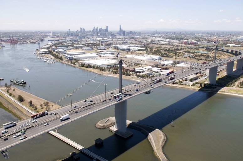
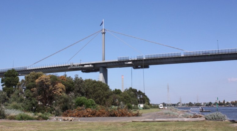
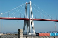
West Gate Bridge crosses the mouth of the Yarra River in Melbourne, Australia. Its 2.6km overall length comprises two concrete box girder high level approach viaducts either side of an 850m long, 5-span cable stayed steel box girder bridge with a 336m main span. The bridge forms a vital link in Melbourne's main East – West transport corridor, the whole of which has undergone a substantial upgrade to provide increased capacity. Flint & Neill used LUSAS Bridge analysis software to undertake global and local finite element modelling to analyse methods of strengthening the steel box girder for increased vehicle loading, by cantilever propping, internal stiffening, and post-tensioning; and for the management of construction loads.
Media
History
Flint & Neill's involvement with West Gate Bridge goes back to the 70s when, following a tragic collapse during construction, it was appointed by Redpath Dorman Long to develop a re-erection scheme for the bridge. After a major re-design and a successful construction the bridge eventually opened in 1978. The bridge was built with 4 lanes of traffic in each direction, and prior to this upgrade was carrying 160,000 vehicles per day and in need of extra capacity. It was required to upgrade the bridge to 5 lanes, as part of a contract between the State of Victoria, Transurban Infrastructure Management Ltd and Citylink Melbourne Ltd, to tie in with the M1 upgrade works. The bridge upgrade works were undertaken by an Alliance in which Flint & Neill had the major responsibility for the assessment and strengthening design for the steel bridge; advice on inspection, operation and maintenance; developing designs for early works improved access; and for producing a current set of electronic as-built drawings from historical documents and original drawings.
Structural overview
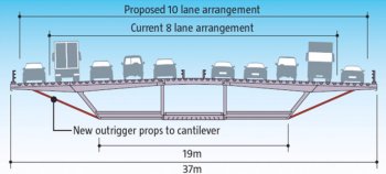
The deck on West Gate Bridge is a continuous steel box girder of 4m in depth with plate thicknesses varying from 10 to 25mm. The overall width including the cantilevers is 37m. Inside, the box girder is divided into three cells by four longitudinal webs and has plated diaphragms every 16m. All plates are heavily stiffened with the majority of stiffeners being the old bulb flat type. The deck is cable supported along its centreline by two sets of cables which pass over saddles at the steel box tower heads and splay out at deck level into cable anchorages within the steel deck box.
Strengthening scheme
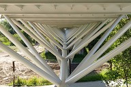
The strengthening solution adopted was to prop the existing cantilevers and turn the existing hard shoulder into a running lane. Other options were considered that required widening the carriageway slightly but studies had shown that it was safe to reduce lane widths (to 3.2m in this case) over short distances without adversely affecting road safety, and this proved to be the least expensive option. As well as propping of the cantilevers a lot of internal strengthening to the deck and towers was required to cope with the additional traffic loading.
Modelling with LUSAS
Very early in the project Flint & Neill decided to create a shell element model of the whole cable stayed bridge structure in LUSAS. Peter Robinson, one of the projects engineers involved said, "Ordinary desktop computers are now capable of running a shell model of the entire bridge, which is great for modelling the distortional and shear lag stresses around the cable anchorages in wide boxes such as West Gate." A rigidity matrix was defined to model the orthotropic effect of the stiffened plates. Linear elastic analysis was used to allow load combinations to be assessed.
Loadcases considered
For the permanent loadcase a survey carried out in 2007 showed that the central span of the bridge had deflected by around 330mm over the years due to the creep and sagging of the cables. Although the stretching of the cables didn't change the tensions in them very much it did add considerably to the stresses in the deck when sagging at mid-span and when hogging at the towers. In the LUSAS assessment model the initial stress in the cable stays was adjusted to represent creep and the deck profile was matched to that of the 2007 survey. An as-built profile was also modelled to allow re-tensioning of the cables in the future.
For live loading, the traffic load definition was specific to West Gate Bridge and was derived from weigh-in-motion data where the weights of vehicles crossing the bridge were recorded and analysed to derive the extreme loading. Traffic loads were generated using Autoloader traffic load optimisation software which required the creation of over 700 traffic loadcases to assess maximum stress along the box girder, and in the bearings and cables. For wind loading static loadcases were derived from the gust buffeting response of a spine model.
Because of the history of the bridge the handling of the construction loads was a particularly sensitive issue, made all the more difficult because the bridge was overstressed under the existing eight lane traffic loading. For reasons of safety, it was required to position concrete barriers along the bridge during the upgrade works which added considerable weight. It was decided to limit the loads during construction to the maximum theoretical 8 lane loading before the strengthening had started. This was achieved by modelling the full sequence of gantry movements and resulted in night time lane restrictions for a long period and restrictions on the allowable movements of gantries.
Detailed modelling
Because Flint & Neill chose to create a shell element model of the whole bridge in LUSAS it was straightforward to refine the mesh in certain areas of interest to investigate localised effects. This had other benefits too as Peter Robinson explains: "Having a single global shell model meant that there was no need to worry about specifying boundary conditions or applying suitable loading as would be required for looking at regions of the structure using separate localised models, and this was a big plus." He continues: "The model also showed how the distribution of loads in the webs and diaphragms of the anchorages took place. It's worth pointing out that for the assessment carrying out the analysis with LUSAS was only half the story. We also had the task of checking against all the element (member) capacities which, for stiffened structures such as this box girder, can be very complex."
Codified checks were carried out to BD56 and to IDWR (Interim Design and Assessment Rules). These rules were drawn up in the 1970s following the collapse of bridges such as Milford Haven and West Gate Bridge and were felt by Flint & Neill to be the most appropriate assessment tool for the upgrade project. Localised modelling and nonlinear analysis with LUSAS was used to improve torsional buckling capacity of the bulb-flats beyond codified values resulting in a reduction of the strengthening required being obtained.
Strengthening required
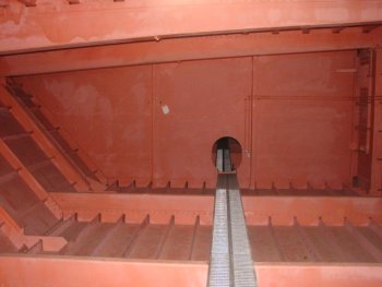
At the start of the strengthening project a lot of work was done to improve the access to the box girder. This saw the enlargement of the central reserve manholes, end pier soffit openings, internal walkways and of the diaphragm and inner web openings where possible. The outside of the bridge has seen the addition of 528 cantilever props, which were installed over a 12 month period using gantries slung beneath the cantilevers. Substantial strengthening was carried out inside the box to the bottom flange and webs. This took the form of extra stiffening to the existing stiffeners and the addition of some new stiffeners. The box walls and diaphragm around the pier bearings required heavy strengthening in an already congested area. Prestressing strands were also used inside the box girder to overcome tension overstress in the bottom flange plate and overstress at the splice plates. The prestressing extends over a 60m length of flange, passing through holes drilled in the flange stiffeners, with plated anchorages at each end. Additional stiffening of the towers was also required requiring the fitting of new plates in the region where the tower penetrates the deck level and for these close tolerance bolts were used to avoid weakening the existing structure.
On completion of the upgrade work the additional traffic lanes were opened for use in June 2011.
"Having a single global shell model meant that there was no need to worry about specifying boundary conditions or applying suitable loading as would be required for looking at regions of the structure using separate localised models, and this was a big plus."
Peter Robinson, Project Engineer, Flint & Neill
A presentation titled 'West Gate Bridge Upgrade' was given by Peter Robinson of Flint & Neill at the 2012 International Bridge Analysis Seminar "Assessment and Rehabilitation of Bridges" held in London on 7th March 2012.
Awards
- Institution of Structural Engineers Structural Awards 2012 : Supreme Award and Structural Heritage Award
- Top title at 2012 Australian National Civil Contractors Federation - Earth Awards for projects over $75million.
- Engineers Australia Engineering Excellence Award Winner 2011
- 2012 Australian Steel Institute, National Steel Design Award for Engineering Projects
- ACE Engineering Excellence Awards 2012, Infrastructure - Small Firms
- British Construction Industry Awards 2012, International Award Winner.
References


- About this
data sheet - Product-ID
6160 - Published on:
08/03/2013 - Last updated on:
17/11/2021